Equalizing Sub High-Frequency Roll-Off
The Background of the Problem
In the measurements section, we talked about the causes of high-frequency roll-off in sub measurements and why it can be harmful to optimization. Such roll-off can be grouped into two categories:
-
Roll-off caused by the measurement technique used
- Measuring using the LFE channel (HDMI channel 4 in Windows) introduces the AVR's "LPF for LFE" into the signal path.
- Measuring through the crossover introduces the low-pass filter of that crossover into the signal path.
-
Roll-off caused by the sub hardware itself or its built-in amplifier.
-
Avoidable problems:
- Failing to use the input of the sub amp (sometimes called "LFE input") that bypasses its internal low-pass filters.
-
Unavoidable problems:
- A sub amp whose LPF cannot be disabled.
- Roll-off caused by the inductance of the sub driver's voice coil.
-
Avoidable problems:
This Technique is for Unavoidable Hardware or Acoustical Problems Only
The technique to be described here is only for fixing unavoidable hardware or acoustical problems, not measurement problems. To use this technique, you must first do the following.
- Use the technique described earlier for taking your measurements to eliminate all AVR low-pass filters from the signal path.
-
Make sure you've exhausted all possibilities for removing from the signal path any low-pass filter that might be present in an active sub's amplifier.
- Read the sub manufacturer's documentation carefully.
- Contact the sub manufacturer if necessary.
Once you have performed those steps, you can use the technique described below. Here we'll assume those steps have already been performed, and the roll-off in the measurements has been verified to have been caused by unavoidable problems, not measurement problems or some avoidable problem with the hardware.
Flattening Out the High-Frequency Roll-Off
Downloading the User Guide Examples: The data for this demonstration are available as getting_started_user_guide.zip. To get results that match the examples, please download and unzip this file before beginning if you haven't already.
The starting point for an optimization that flattens high-frequency sub roll-off should be a configuration that's been optimized for maximum SPL and nothing else. Such a configuration is found in the user-guide-2.msop project from our previous examples. Open up that project and save it as user-guide-6.msop to avoid accidentally saving it under its original name.
The reason for starting with a configuration that's only been optimized for SPL is that an SPL optimization tries to get all the subs to be as close as possible to being acoustically in phase with one another. This greatly reduces response "suck-outs" and "hash" that may appear at high frequencies. The resulting response at the MLP after the optimization should resemble the MLP's so-called natural response on a graph.
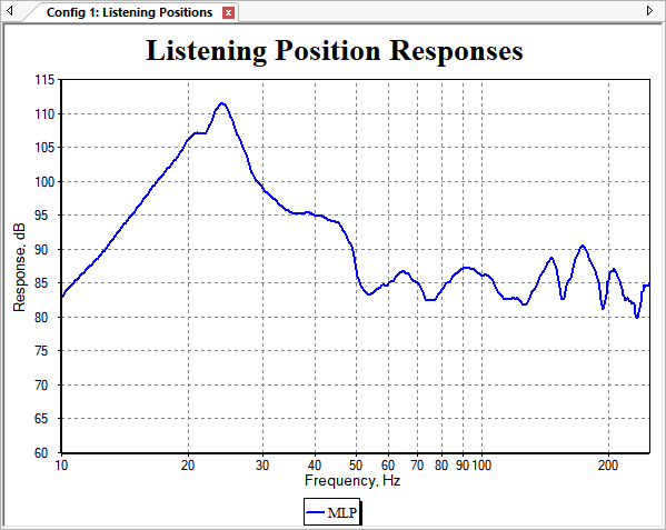
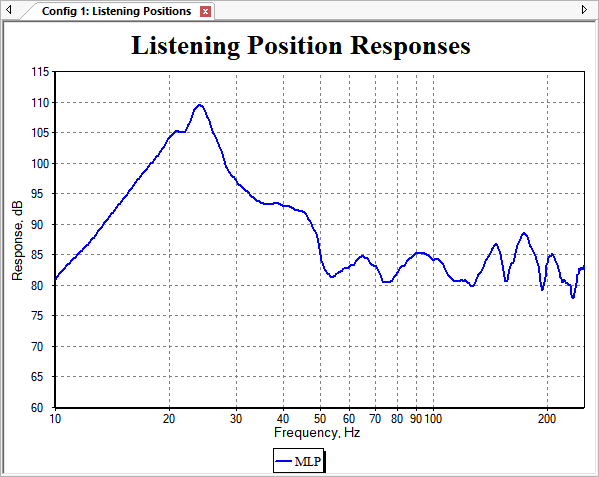
Using the technique described previously, toggle the display of the Pos 1 and Pos 3 traces to be off so that only the MLP trace is shown. Press Ctrl+G to bring up the graph's property sheet, and on its Axes property page, change the maximum x-axis frequency to 250 Hz from its previous 200 Hz value. The graph should look as below.
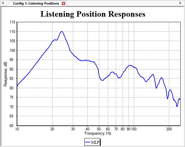
Earlier, we observed that this response could be thought of as having three regions. The response in the region from about 50 Hz to about 120 Hz could be considered to be at a "normal level". The response at frequencies below 50 Hz is heavily influenced by a large modal peak, giving a boost of about 30 dB at around 25 Hz. Above about 120 Hz is the roll-off region. We'd like to get rid of that roll-off.
We can think of the solution of this problem as the extension of the frequency range of the "normal level" so that it reaches all the way to 250 Hz.
Do Not Use PEQs to Flatten the High-Frequency Roll-Off
PEQ filters are appropriate for equalizing peaks and dips when used as shared filters, and to minimize STSV caused by room modes when used separately for each sub. But when trying to counteract a steady "tilt" in the response, such as what's occurring here at high frequencies, a high-shelf filter with some boost is the correct solution. Let's look at how that's done.
Using a High-Frequency Shelving Filter
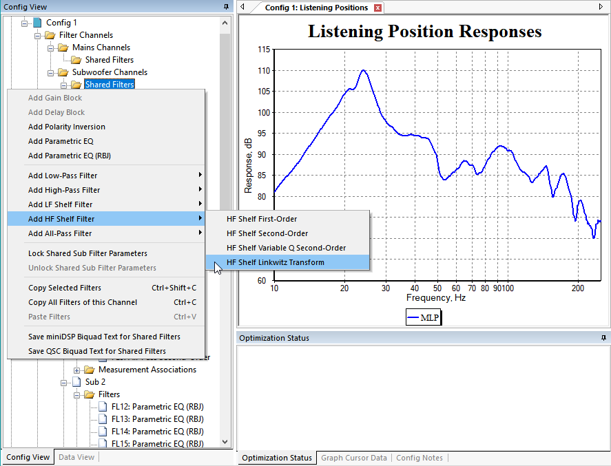
As mentioned above, a high-shelf filter is the correct solution, but there is no high-shelf filter in this MSO project. That means we have to add one manually to the shared sub filters, using the technique described previously. Instead of using an HF Shelf Variable Q Second-Order filter, we'll make use of the uncommon HF Shelf Linkwitz Transform filter type. Add one of these filters as shown below.
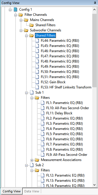
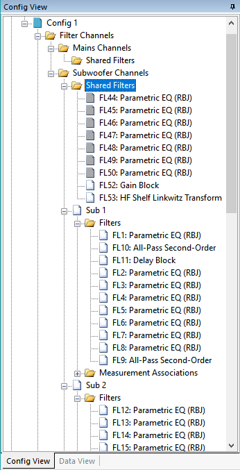
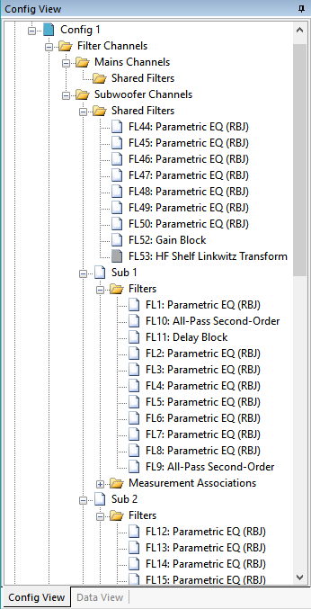
After adding this filter, the Config View should look as below.
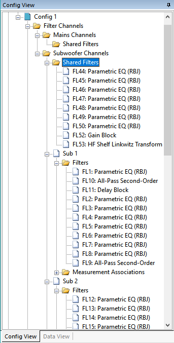
For reasons that we'll explain in a later section, we will keep the total number of filters in this configuration the same. Since we just added one, we should delete a different one to make up for it. Let's delete the filter FL51. Don't delete the gain block. To delete FL51, just select it and hit the Delete key. After doing that, the Config View should look like the image below.
Now we need to set the parameter value limits of the HF Shelf Linkwitz Transform filter FL53 that we just added. For PEQs and all-pass filters, there are property pages of the Optimization Options property sheet dedicated to setting these limits for many filters at once. All other filter types are rarely used compared to PEQs and all-pass filters though, so there aren't any such dedicated property pages for them. This means the parameter limits of FL53 need to be set on an individual filter basis. This is done in the Properties window on the right side of the MSO main window.
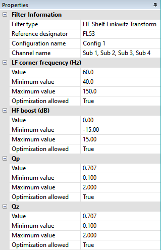
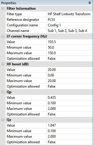
Select the HF Shelf Linkwitz Transform filter FL53 in the Config View and observe its properties in the Properties window. This window should look as below.
Let's change some of these parameter limits. Recall that we're only trying to affect the response at 50 Hz and above. When this shelving filter is boosting the high frequencies, the LF corner frequency is the frequency at which the response just begins to rise. Let's set that to 50 Hz. We only want boost for this filter, so change the Minimum value of the HF boost to zero. We'll let the Maximum value of the HF boost go all the way to its highest possible value of 20.0 dB. After making these changes, the Properties window should look as below for FL53.
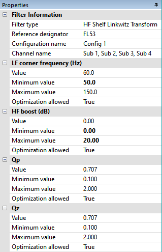
As mentioned earlier, after you modify property values in the Properties window, they are displayed in bold type as you see above.
Choosing the Optimization Type
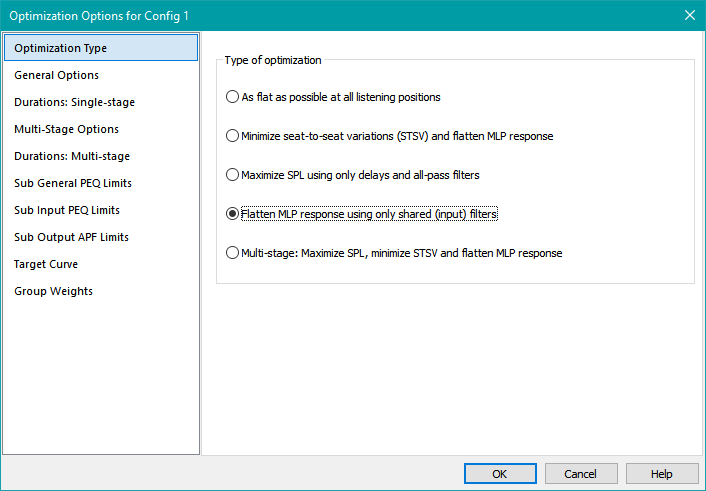
Version 2 of MSO adds the ability to do conventional equalization. This is done using the Flatten MLP response using only shared (input) filters optimization type on the Optimization Type property page of the Optimization Options property sheet. According to the linked description, when you run this type of optimization, MSO temporarily locks all parameters of all filters except those in the shared sub path. It then adjusts only the shared sub filter parameters to force the MLP response to the target curve. Since the default target curve is a flat response, this optimization type is exactly what we need to flatten the high-frequency roll-off of this example.
Preparing the Configuration
We want this optimization to do two things:
- Optimize the response only at the higher frequencies, from 50 Hz to 250 Hz.
- Only adjust the high-shelf filter FL53 to flatten the response. No other filters should be adjusted.
We can achieve the first goal by setting the optimization options, which we'll do shortly. To achieve the second goal, we'll need to lock all the parameters of some filters so the optimizer can't adjust them. We'll look at that next.
If we were to run the optimization without locking any filter parameters, MSO would try to adjust all the parameters of all the shared sub filters to flatten the high-frequency roll-off, including the seven PEQs FL44 through FL50. But we only want it to adjust the high-shelf filter FL53 to do this. Also, in the previous topic, we talked about the essential nature of the shared gain block (FL52 in this case) to achieve the best possible equalization. Because of the key role played by the gain block, we need to also allow the optimizer to adjust it in addition to the high-shelf filter FL53. Here's how to do it.
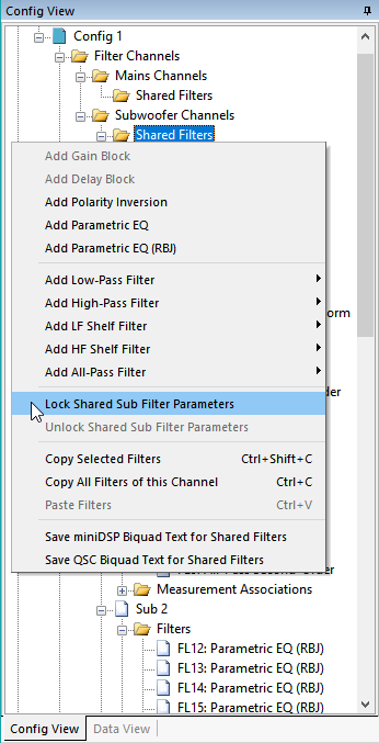
First, in the Config View, right-click on the Shared Filters node under Subwoofer Channels and choose Lock Shared Sub Filter Parameters from the context menu as shown below.
When done, the Config View should look as below.

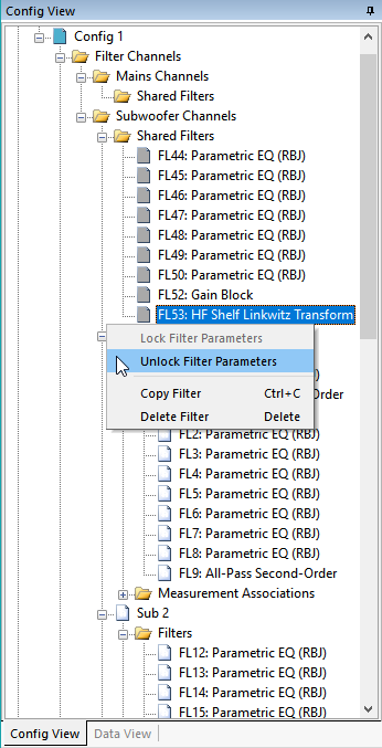
Now all the shared sub filters have all their parameters locked. We need to unlock the parameters of the high-shelf filter FL53, and as mentioned previously, the gain block FL52 so the optimizer can adjust them. First right-click on the HF Shelf Linkwitz Transform filter FL53 and choose Unlock Filter Parameters as shown below.
Repeat this operation (not shown) for the gain block FL52. When done, the shared sub filters should look as below.
Now that we've locked all the parameters of all the input channel filters except for the HF Shelving filter (FL53) and the gain block (FL52), what about all the unlocked filters in the four output channels? Don't we need to lock them too?
When MSO does an optimization using the Flatten MLP response using only shared (input) filters optimization type, it temporarily locks all parameters of all filters except those in the shared sub path. In other words, it temporarily locks all the filters in all the output channels. What we now have is the following situation.
- We've locked all the input channel filters except for the HF Shelving filter and the gain block.
- As part of the Flatten MLP response using only shared (input) filters optimization type, MSO will temporarily lock all the output channel filters during the optimization.
This means no further filter locking is needed on our part. All we need to do now is specify the optimization type and the restricted frequency range over which we want to optimize.
Setting the Optimization Options
Open up the Optimization Options property sheet as we've been doing, and choose Flatten MLP response using only shared (input) filters on the Optimization Type property page as shown below.
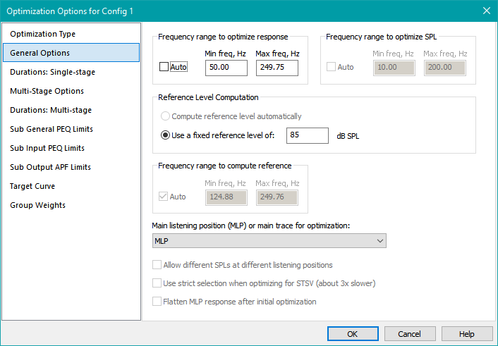
Next, on the General Options property page, under Frequency range to optimize response, uncheck Auto. Enter a value of 50 for Min freq, Hz and a value of 250 for Max freq, Hz. MSO will give an error message, saying that the frequency of the input data only goes up to 249.75 Hz. Enter 249.75 for Max freq, Hz to fix this problem.
The closest round number to the so-called normal level that we've been referring to looks to be around 85 dB, so enter 85 in the reference level edit control. Per the previous discussions about the final reference level being mostly cosmetic, its function here is to just set a target for the shared gain block. After entering the data, the result should look as below.
At this point, we could carefully specify the optimization duration, but this optimization will run very quickly since there is so little to do. We'll just run it, and when the data stops changing, stop the optimization manually. This means we can just press OK to dismiss the Optimization Options property sheet now and accept all the chosen options.
Running the Optimization
Next, run the optimization in the usual way. It should converge very quickly, so just stop it manually when the optimized results stop changing. The final result is shown below.
We can see the effect of the 85 dB reference level in the plot. The gain value of the gain block is adjusted to make the errors around the 85 dB level from 50 Hz to 250 Hz more or less symmetrical to minimize the flatness error. We don't actually care about the final gain value of the gain block though. We could just as well set it back to 0 now, as the work of the gain block in helping the optimizer to minimize the flatness error is now done.
Let's use the techniques described above to set the gain value of the gain block back to 0. Select the gain block in the Config View and observe its value in the Properties window. For this example, the gain value ended up being 1.94 dB. Change this value to 0 dB using the Properties window. The new plot should just be shifted down slightly as below.
We'll use this project as the basis for some later optimizations. For those optimizations, we'll need to use the shared sub filters that we locked above earlier. This means we need to unlock those filters. We'll also want to take advantage of the benefits that the high-shelf filter gave us of getting rid of the high-frequency roll-off. The parameter values of this high-shelf filter were calculated to meet a very specific need, so we don't want later optimizations altering any of the parameter values of the high-shelf filter. This means we need to lock it.
Using the techniques described earlier, do the following.
- Right-click on the Shared Filters node under Subwoofer Channels in the Config View and choose Unlock Shared Sub Filter Parameters from the context menu.
- Right-click on the HF Shelf Linkwitz Transform filter FL53 in the Config View and choose Lock Filter Parameters to prevent later optimizations from modifying it. All the shared sub filters except the HF shelving filter should now be unlocked. The results should be as shown below.
Now that the desired final states of all the filters have been set, save this project as user-guide-6.msop.
Let's look at how the parameters of the HF shelving filter turned out. Select FL53 in the Config View and observe its parameter values in the in the Properties window. The properties of the HF shelving filter are shown below.
One thing that stands out and is cause for concern is the high-frequency boost of 20 dB. This needs some further investigation. Later in the User Guide we'll find out how to plot the response of the filters in a DSP channel, but for now we'll just look at some results. Here is the response of the shelving filter by itself.
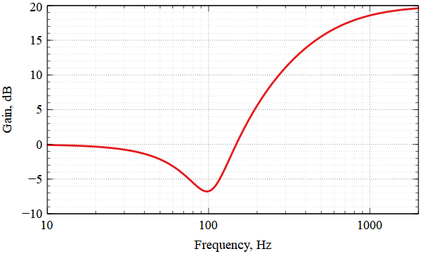
This confirms the high-frequency boost. One odd feature is the response dip at 100 Hz. For a high-shelf Linkwitz transform filter with boost, if the "zero Q" (Qz) is greater than 0.707, there will be a response dip near the LF corner frequency before the response rises. The value of Qz is 1.847, resulting in the dip. If the "pole Q" (Qp) were greater than 0.707, there would be a peak before the response levels out at high frequency. But the value of Qp is 0.435, so a gradual rise is seen.
The dip at 100 Hz is providing some equalization to drop down a peak in the un-equalized response. This is why the high-shelf Linkwitz transform filter was chosen instead of a more conventional high-shelf filter.
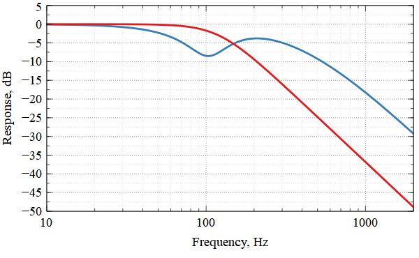
Is that 20 dB of high-frequency boost a problem? Keep in mind that in a complete system, the signal goes through a low-pass filter before it even gets to the DSP device. Let's look at the response of an 80 Hz LR4 filter, along with the combination of the 80 Hz LR4 with this shelving filter. This combination is shown below.
The red trace is the 80 Hz LR4 filter by itself, while the blue trace is the combination of the 80 Hz LR4 filter with the high-shelf filter. Fortunately there is no net boost anywhere. This combination seems safe.
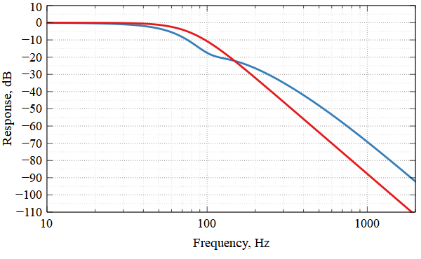
A less straightforward problem is what happens in the system with an LFE input. There is some standardization of 120 Hz as the cutoff frequency of an "LPF of LFE" filter, but what type of filter is it, and what order? Let's assume a second-order Butterworth filter and look at a similar plot.
This is cause for some concern. One might decide on whether this solution is acceptable based on the cause of the roll-off we're trying to correct.
Suppose the roll-off we're trying to correct is due to a sub amp with an internal LPF that can't be disabled. We could think of the sub amp as internally consisting of an LPF at its input, combined with a flat-gain amp after it. In such a case, the signal "seen" by the flat-gain amp would be a version of what's in the image above, but with an additional low-pass filter (its own internal one) applied to it. This suggests that for such a situation, a large HF boost as shown above, upstream of the amp, would be safe - because the flat-gain portion of the amp "sees" the additional low-pass filtering.
On the other hand, suppose the roll-off we're trying to fix is due either to purely acoustical causes (room modes) or to the inductance of the voice coil of the subwoofer driver. In such situations, there isn't any non-defeatable LPF further down the line that's limiting the high-frequency content seen by the sub amp. For those cases, it's probably wise to limit the maximum HF boost in the shelving filter to something like 10 dB.
For this case, we'll assume we're correcting a non-defeatable LPF in the sub amp, so we'll keep the shelving filter as-is for the next example.