Distortion Matching For Dissimilar Subs
Maximizing SPL Requires Careful Sub Setup
When the subwoofers you're using aren't all identical, extra steps are needed to ensure that the highest SPL you can get from your system is not limited by subs having a lower maximum SPL than your most capable ones. The purpose of this article is describe the steps necessary to achieve this, as well as why they are necessary.
SPL Maximization Tries To Acoustically Match Subwoofer Phase Responses
One question that often comes up is, "How much SPL increase can I expect using multiple subwoofers?" This has been the subject of web articles and forum posts over the years . Maximizing SPL at any frequency and listening position is done by using DSP to manipulate all the subs' acoustical responses to be in phase at that frequency and listening position. By using a combination of delay and all-pass filtering for each sub, this phase matching could in theory be extended over the subs' full frequency range to be made nearly perfect at any one listening position. Achieving this at multiple listening positions is not possible, but in MSO, an averaging approach is used to prevent phase errors from getting too large at any combination of listening position and frequency.
The so-called "natural responses" can be plotted on graphs. These display the response you would get at each listening position if you could achieve the impossible goal of subwoofer acoustical phase matching at all frequencies and listening positions at once. Although these responses cannot be achieved in practice, comparing responses achieved by a standalone SPL optimization to the natural responses is a useful way of judging how close the acoustical phase matching is.
SPL Maximization Tries To Keep All DSP Channel Gains Equal
In addition to acoustical phase matching of the subs, their relative level is important for achieving the highest possible SPL. This is easiest to understand when considering a system having identical subs with identical amplifiers, with all amplifiers adjusted for identical gains. If all subs are driven identically in this way, all of them will reach their SPL limit at once, with no one sub acting as a weak link. The term "gain matching" is used in online forums to describe this condition.
When using optimization to maximize SPL with MSO, an error measure called the "SPL penalty" is computed. The SPL penalty would be zero if all DSP channel gains were equal over the optimization frequency range, and the acoustical responses of all subs were in phase with each other at all listening positions over this frequency range. Thus minimizing the SPL penalty involves trying to make all DSP channel gains as equal to one another as possible over the optimization frequency range. The equal gain condition is forced when using standalone SPL optimization and relaxed slightly for multi-stage optimization in order to reduce seat-to-seat response variation.
But what happens if all the subs are not identical? Doesn't this approach break down? It might appear to, but in practical situations it just means that matching sub levels via the popular "gain matching" approach no longer necessarily achieves the highest possible SPL. This means that setting the relative sub levels becomes more involved when using dissimilar subs.
The Usefulness of Equal DSP Channel Gains Isn't Limited to Identical Subs
When all subs are identical and their amplifier gains are equal, it's not difficult to see that having equal DSP channel gains will, with all else being equal, maximize the system's SPL capability. When all subs are not identical, it's helpful to think of matching the DSP channel gains as preserving the relative sub gains you set prior to performing the sub measurements. With dissimilar subs, the question then becomes how one might set the relative sub gains so that all the subs reach their SPL limit at once.
There is no perfect answer to that question, but in general, it means that for the same signal level at the input of the DSP device, the relative sub gains must be set so that the less capable subs are running at a lower SPL than the most capable ones.
Using Distortion Matching To Set Relative Sub Gains
Distortion measurement is a good way to assess how hard a sub is being driven relative to its capabilities. Although there is no perfect way to set the relative sub gains to guarantee that all the subs reach their SPL limit at once, altering relative sub gains of less capable subs to try to match their distortion to that of the most capable one is a useful technique to ensure that all subs are driven equally hard relative to their capabilities.
Before getting into the specifics of using distortion matching, it's necessary to first discuss some technical aspects of sub distortion measurement. The most important topic is the appropriate use of the REW Use harmonic frequency as ref distortion measurement option.
To understand what this option does, let's first look at the system block diagram below that includes a distortion-producing device, followed by a filter that introduces no distortion.

Suppose the source of distortion is an electronic device and the filter following it is an electronic filter. Also suppose that the distortion-producing device produces only second-harmonic distortion, and that its distortion of a 100 Hz signal is large, say 10 percent. This is the same as saying the second harmonic distortion component at 200 Hz is 20 dB down from the 100 Hz fundamental at the output of the distortion-producing device.
What would happen if the filter following the distortion-producing device had a gain of 0 dB at 100 Hz, but at the second harmonic of 200 Hz, it is 40 dB down? That is the same as saying that the filter attenuates the second harmonic by a factor of 100 relative to the fundamental. The filter alters the spectrum of the distorted waveform. Instead of the second harmonic being 20 dB down from the fundamental as it is at the output of the distortion-producing device, it's now 60 dB down because of the effect of the filter. If we were to measure the distortion at the filter output without any additional processing, it would measure 0.1 percent, rather than the actual 10 percent value of the distortion-producing device.
If we only have access to the output of the filter and not the output of the distortion-producing device, then to get an accurate distortion measurement of the distortion-producing device itself, we'd need to "back out" the effect of the filter, boosting the measured second harmonic by a factor of 100 to counteract the effect of it having been cut by a factor of 100 by the filter. That is what the REW Use harmonic frequency as ref distortion measurement option would do in this situation.
This technique assumes that the frequency response variation of the overall system is dominated by the distortion-free filter that follows the distortion-producing device.
In the case of a subwoofer distortion measurement at some listening position, the distortion-producing device in the diagram above is the subwoofer, while the distortion-free filter is the modal response of the room from the subwoofer position to the measurement position. This modal response of course depends on the location of the sub in the room. Because the modal response shapes the spectrum of the distortion in different ways depending on the sub's location, if no extra processing were done, we'd expect identical subs driven identically to have different measured distortion if they are in different locations in the room. In theory, we can eliminate that effect by using the REW Use harmonic frequency as ref distortion measurement option.
How Might the REW Use Harmonic Frequency as Ref Option Fail?
Since this technique assumes that the system frequency response is dominated by the distortion-free filter on the output side of the diagram above, if this assumption were violated, a less-than-ideal correction using this option might be expected. This assumption could be violated by a filter having a strong frequency response variation being placed ahead of the distortion-producing device on the input side, or if the response variation of the distortion-producing device were not negligible compared to the distortion-free filter. For this reason, when you measure sub distortion you should avoid measuring the sub with any filter in place, such as the crossover or even the "LPF for LFE". A method to avoid all LPFs when measuring subs is described in the measurements section.
We can test this REW option by taking two identical gain-matched subs in different locations in the room, measuring them both at the same listening position and comparing the measured distortion results with and without the Use harmonic frequency as ref option.
Testing the REW Use Harmonic Frequency as Ref Option
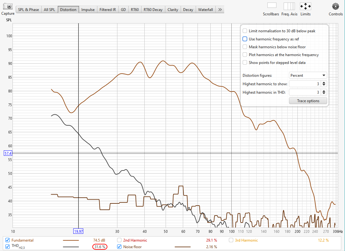
First we need to set up the simplest possible distortion measurement in REW. The easiest way to do this is to look at only a single measurement. Set up REW to graph a single measurement, then press the Distortion button above the graph. Press the Controls button at the top right. Refer to the graph below when following the instructions after it.

Refer to the figure above to set up the initial distortion graph controls.
- Uncheck all five checkboxes.
- Set Distortion figures to percent.
- Set Highest harmonic to show to 3.
- Set Highest harmonic in THD to 3.
A couple of things are noteworthy from this graph.
- The distortion near 20 Hz is 31.6 percent (circled in red near the bottom). This is suspiciously high for an 18 inch sub playing at a maximum SPL of around 90 dB.
- The distortion is below the noise at frequencies above 50 Hz, meaning that its measured value above 50 Hz is likely to be unreliable. More will be said about this later.
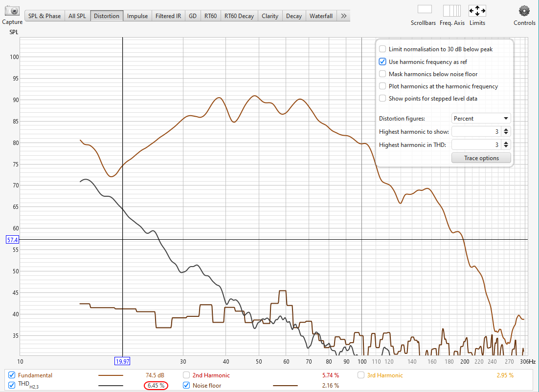
Now let's try the Use harmonic frequency as ref option by checking the corresponding Controls checkbox. The result of selecting this option is shown below.

This result seems suspicious as well. After the discussion above about the Use harmonic frequency as ref option, we'd expect the shape of the distortion curve to change, as this option corrects the computed distortion for response variations with frequency. On a positive note, the new graph now shows the THD near 20 Hz has changed to a more believable 6.45 percent. But that is the only difference between the two graphs. What happened?
The REW documentation for this topic reveals why the plot traces didn't change. It says the following.
"Note that this option [Use harmonic frequency as ref] will not affect the traces when the plot is not normalized, but will still affect the values in the legend if the distortion figures are set to read in percent or in dB relative to the fundamental."
To fix this, we'll need to set the y axis to percent so we can see the change in the graph traces caused by the Use harmonic frequency as ref option. While we're at it, we'll switch to the REW Overlays Window so we can compare the distortion of multiple traces on the same graph, and restrict the frequency axis to only show the distortion from 15 Hz to 50 Hz (since it goes below the noise above 50 Hz).
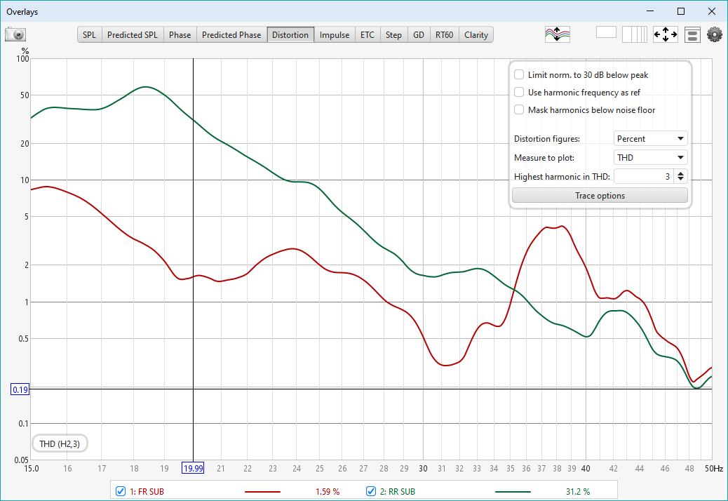
Let's have a look at a distortion comparison of two identical, gain-matched subs. The only difference between the two subs in the graph below is their position in the room. First, we'll look at the data without the Use harmonic frequency as ref option. The comparison plot is shown below.

This is another suspicious graph. Despite the subs being identical and gain-matched, the measured distortion seems radically different between the two. Near 20 Hz, one sub shows 1.59 percent THD while the other shows 31.2 percent. Between 18 and 19 Hz, one sub has distortion between 2 and 5 percent, while the other is over 50 percent.
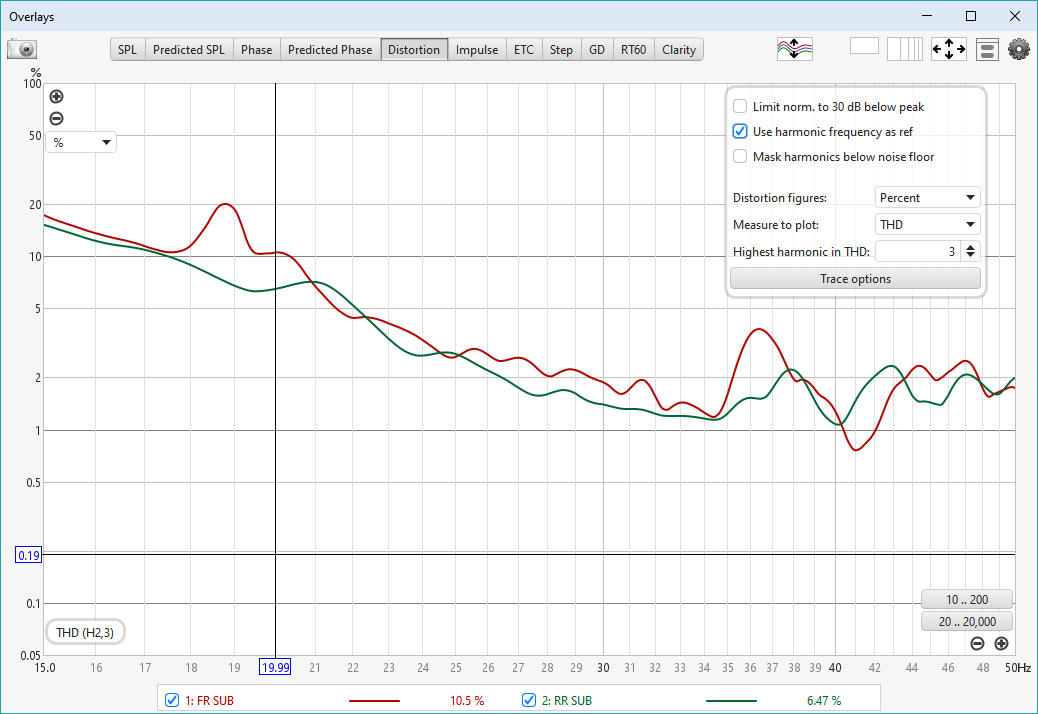
Because the subs are identical, a necessary condition for trusting the distortion data is for the two distortion traces to closely match. Let's see what happens when we enable the Use harmonic frequency as ref option.

That's more like it. Although the distortion matching isn't perfect, it's way better than it was without the REW Use harmonic frequency as ref option. Given all the uncertainties of acoustical measurement, this may be as good as we can do.
It's Best To Use Long Sweeps When Measuring Distortion With REW
Using a sufficient number of samples is essential for obtaining accurate distortion measurements with REW. The REW documentation quoted below gives important insight on REW measurement settings that should be used.
Impulse responses measured using logarithmic sweeps separate distortion from the linear part of the system response. The distortion components appear at negative times, behind the main impulse. Analyzing the frequency content of these components allows plots of distortion harmonics to be generated. The longer the sweep, the better the distortion components are separated from each other. Sweeps of 256k or shorter should start at 0 Hz to prevent an artificial rise in distortion at the lowest frequencies due to the reduced low frequency bandwidth of the resulting impulse response. When measuring a system with high distortion levels use a long sweep setting (e.g. 1M or higher), at shorter sweep lengths the harmonics may affect each other giving misleading results.
Summary of Results So Far
- To maximize your system's SPL capability when dissimilar subs are used, the relative sub levels should be adjusted so that when the system SPL is near the maximum of its capability, all subs are driven equally hard relative to their capabilities.
- The best known way of measuring a sub's SPL capability is to perform distortion measurements on it. REW is an excellent tool for this.
- REW has a distortion measurement option called Use harmonic frequency as ref, but without some evaluation, it's unclear whether or not it should be used.
- One necessary condition for good distortion measurements is to achieve good distortion matching of two identical subs, driven identically but placed in different positions in the room and measured at the same listening position.
-
Evaluation of the Use harmonic frequency as ref REW distortion measurement option for comparing the distortion of identical subs gives the following results.
- Poor distortion matching was obtained without the option.
- Good distortion matching was achieved with the option.
- Therefore the Use harmonic frequency as ref REW distortion measurement option should be used when matching distortion of different subs. This option can be enabled at any time without requiring a new measurement.
- Use long sweeps (e.g. 1M or higher) starting at 0 Hz for the most accurate low-frequency distortion measurements of subwoofers driven to high distortion levels.
Recommended Method for Distortion Matching
Given the results so far, the following method is recommended for distortion matching.
- All subs should be measured in their actual final locations, and all measurements should be taken at the MLP.
-
Make sure all subs to be used are connected to the DSP device, and the DSP device is cleared of all filters, gains etc.
- Exceptions to the "no filters" rule can be made for high-pass filters used with DIY vented-box subs.
-
Measure the response and distortion of the most capable sub at an SPL approaching its practical limit.
- A suggested distortion limit is 10 percent at 20 Hz.
- Using the absolute SPL plot as shown in the first measurement figure above, determine the upper limit of the distortion frequency range by finding the frequency for which the measured distortion reaches the noise level.
- Choose the Use harmonic frequency as ref REW distortion measurement option with all distortion measurements.
- Adjust the sub's amplifier gain as needed to reach the target distortion level.
-
Once the correct sub drive level has been determined, display the distortion result in the REW Overlays Window as shown in the figure above.
- The frequency range of this plot should be from the lowest measurement frequency to the upper limit determined by noise considerations in step 3 above.
- For any other subs that are identical to the most capable one determined in step 3, set their amplifier gains to be identical to the value of the first one as determined in step 3.
-
For each sub having a lower SPL capability than the most capable one, measure its response and distortion.
- Add the distortion plot to the REW Overlays Window.
- If its distortion doesn't match the more capable sub, change this sub's amplifier gain to get it to match as closely as you can.
- If the subs are dissimilar enough, especially if one is sealed and the other vented, the distortion curves may be difficult to match and some judgment will be necessary.
- Repeat step 6 for all remaining subs.
-
Once all the gains are set to match the distortion curves, keep these relative gain settings and use them in the measurements you perform for MSO.
- For the MSO measurements, you may want to back off on the overall sub level while preserving the relative sub gains to avoid having too much distortion in the measurements.
- If your sub amplifiers don't have adjustable gain, or you run out of gain adjustment and need to use the DSP device to set relative gains, these DSP gains need to be in place for the measurements, and would constitute an exception to the rule of measuring with the DSP completely cleared out.
Using Mismatched Amplifier Gains to Achieve Subjective Preferences
Even if all your subs and sub amps were identical, there are still some situations for which you might not want to gain-match the subs, and instead rely on some subjective considerations for setting the relative sub levels.
Suppose one of your identical subs were a near-field sub. If it were gain-matched to the others, it might be too loud and overpowering. The solution is to turn the near-field sub down to the level you want, then do all the measurements with that subjective preference of relative sub gains in place. MSO doesn't "know" that turning up the near-field sub would increase SPL capability. Instead, the SPL maximization will try to maintain the same relative sub levels you set before you did the measurements.
In that state, MSO will try to give the best SPL possible, given your choice of relative sub gains that prevents you from being overpowered by the near-field sub.